Schematic

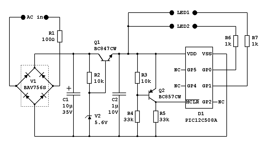
Figure 1. IR transmitter schematic.
The components shown in the schematic are the ones I use in the final design. They are chosen mainly because of their small size. In my prototypes, I have used slightly different components, but this does not have any effect on the function.
If you don't care about the size, you can replace V1 with four standard diodes, e.g. 1N4148, and the transistors can be replaced by some other types e.g. BC547B instead of BC847CW and BC557B instead of BC857CW. You can also use a PIC12C508 instead of the PIC12C508A version. Only the 'A' version comes in the smaller package (/SN package option).
Pulse generation
The pulse generation is done by the PIC processor. The rest of the components are power supply and reset circuitry. The transmitter sends out two different 8-bit codes, one for each LED. This makes it possible to detect the direction of the loco. I let the codes differ only in bit 7 and the parity bit. This gives a very simple PIC program.
Data is sent as 'LED off' pulses, where a '0' or a '1' is coded by the length of the pulse. Each data sequence consists of:
An example of a pulse sequence with hexadecimal data 1A (decimal 26). High = LED on:

Figure 2. IR transmitter pulse sequence example.
The PIC12C508A processor has to be programmed with an individual code for each loco. The PIC program for the transmitter can be found here:
In the HEX file, you can change the value with e.g. IC-prog. You find the value 0C0A at hexadecimal address 100. The two least significant hex digits (0A) is the data value.
Power supply and reset circuitry
The diode array V1 forms a rectifier bridge, that converts the incoming AC or digital signal to DC. Resistor R1 is there to limit the peak current through the diodes to well below the specified maximum value of 450 mA. Capacitor C1 is the bulk decoupling capacitor. It must be rather large to overcome the power drops that occur due to bad contact between the wheels/pick-up shoe and the track. The bulk decoupling is placed before the voltage regulation, because it is here you get the most effect out of it. But this also means that you need to have a high voltage rating, at least 35 V.
R2, V2 and Q1 is the voltage regulator. The function is equivalent of a standard 7805 regulator, but the discrete solution is smaller, and probably also cheaper. C2 is another decoupling capacitor, to filter out the switching noise from the PIC.
R3, R4, R5 and Q2 is the reset circuitry. When the voltage drops below a certain level (approximately 2.8 V), the transistor Q2 turns off, and the resistor R5 will pull the MCLR pin of the PIC down to 0. This will prevent a so-called "brown-out condition", which otherwise may occur if the supply voltage to the PIC drops below 2.5 V without going all the way down to zero.
The two resistors R6 and R7 are there to limit the current to the two LEDs to a suitable value.
Prototype
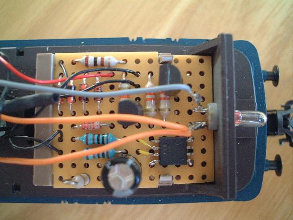
I have built two prototypes and mounted them in two of my locos. Here is a picture of the prototype, mounted in a Märklin 3374. At the same time, I converted the 3374 to fully regulated digital, with the 60901 conversion kit.

Figure 3. IR Transmitter prototype.
Final design
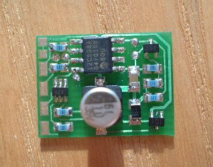
The final version of the transmitter electronics is a 18.5 x 14 mm single-sided circuit board. My friend and colleague Stefan Eskilsson designed the layout. A PDF drawing of the layout can be found here.
I have assembled the transmitter boards, and built them
into most of my locos. The PIC processor is mounted first, together with
five temporary wires connected to the five
round soldering pads. The five wires are used when programming
the PIC, and are removed before the rest of the components are mounted.
The square soldering pads to the left are the connections for power and for the two IR LEDs.

Figure 4. Final IR transmitter board.