This signal module is designed to control Viessmann light signals directly from the PC via a 9.6 kbaud serial port. The module has soft light change. It only controls the signal lights, no train control is included. Each module can control 16 LEDs. I have used small transistors (BC547B) and the output is therefore limited to 50 mA per port. The signal connectors are 3-pole female connectors mounted on ribbon cable. The resistors and diodes on the Viessmann signals can be plugged directly into these connectors.
The unit should be powered with 12-14 V DC. The power and the serial signal is connected via the connectors X9 and X10. I use 6-pin headers and wire them symmetrically. In this way I can use standard ribbon cable and ribbon cable contacts without thinking of polarization. I mount two identical contacts to allow daisy chain connection. The serial input is protected with a resistor and clamped with a zener diode. This allows direct operation from the PC serial port, but standard TTL levels can also be used.
Schematic
Figure 1. Signal module schematic.
Circuit board
I build the modules on Veroboard. I need too few to justify the manufacturing of a real circuit board. Below is a picture of the wiring and component placement, seen from the solder side:
Figure 2. Component placement and wiring, seen from the solder side.
Here is a picture of the module. On some modules (like this one), the 1.0 µF capacitor C2 is a surface mounted capacitor on the solder side. Note the green wire going over the outgoing wires. This is used to fix the outgoing wires to the board.
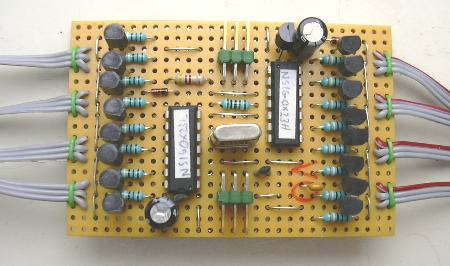
Figure 3. The component side of the module.
Serial communication protocol
The serial communication is 9.6 kbaud, 8 bits, no parity. A command sequence to a module consists of an address byte followed by one or several command bytes.
Figure 4. Serial command protocol.
PIC program
The PIC processor program for the decoder can be found here:
The device address must be changed for each module to be built, and you must also change the program to select the upper or lower 8 ports of the module. The program given here has device address 0x00 and selects the lower 8 ports. If you use the .asm file, the address and the selection of upper/lower ports are defined in the beginning of the program. In the .hex file, you find 0x0C00 at position 0x0100 and position 0x0109 in the code. The two lower hex digits is the device address. At position 0x0112 you find the code 0x0C80. For the upper 8 ports, this should be 0x0C88 instead. The values can be changed directly in the hex code with e.g. IC-Prog. Note that bit 7 in the device address must be 0.
Signal connector
A connector for the signals is shown below:
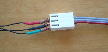
Figure 5. Signal connector.