The presence of a train on a certain track segment can be detected by the current it draws. This is a more complicated solution than the simple contact track, where the wheels cause contact between the left and right rails. However, contact tracks rely on that the train has good contact to both rails. With Märklin C and M tracks it is also easier to create an isolated center rail segment than to isolate one of the side rails.
Current sense can be built in two different ways. With the first method, you connect a resistor and/or a pair of diodes in series with the power feed to the detection segment and detect if there is a voltage over the resistor/diodes or not. The other method uses a signal transformer to detect the current. The signal transformer solution gives a galvanically isolated detection circuit, and it has virtually no impact on the digital signal to the track. The drawback is that it can only detect AC or digital signals. DC current draw can not be detected.
I have designed a current sensing module based on the signal transformer principle. The module will not be used on my own layout (I have my train recognition system), but on another layout where I am contributing.
Each module contains circuitry for detection on two track segments. The module will detect current draw down to around 10 mA when the Märklin/Motorola format is used. This means that it can detect a digital loco standing still with all lights off. The sensibility is probably around the same when used with mfx or DCC, but I have not measured the limit for these protocols yet. It works with conventional AC as well, but with reduced sensibility.
The module requires 5 V power supply. I have placed the power and ground symmetrically on the connector X4, with the two output signals in the middle. The signal transformers are made from ferrite cores that I have taken from scrapped PC motherboards. The clamping diodes on both sides of each signal transformer might not be needed, but I want to be sure that there cannot be any voltage spikes under any conditions.
Schematic
Figure 1. Current sensing train detection module schematic.
Circuit board
I have built the module on Veroboard. Below is a picture of the wiring and component placement, seen from the solder side:
Figure 2. Component placement and wiring, seen from the solder side.
Here are pictures of the module from the component and solder side.
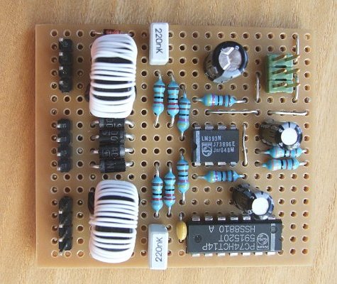
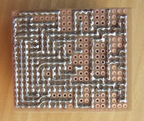
Figure 3. The component and solder sides of the module.